vPC Data Plane Traffic Flow
vPC performs loop avoidance at the data plane by implementing certain forwarding rules. The most important forwarding rule for a vPC is that a frame that enters the vPC peer switch from the peer-link cannot exit the switch from a vPC member port. This packet can exit on any other type of port, such as an L3 port or an orphan port. This rule prevents the packets received on a vPC from being flooded back onto the same vPC by the other peer switch.
When communicating with external networks, the vPC domain prioritizes forwarding through local ports, except in certain situations such as traffic forwarding to orphan devices and flooding traffic (broadcast, multicast, and unknown unicast traffic), which uses the vPC peer-link. For forwarding regular vPC traffic, vPC peer-link is not used to forward data packets. An exception to this rule is when a vPC peer switch has lost all its member ports, resulting in orphan ports on other peer switch. In this case, the vPC peer switch, where the member ports are up, will be allowed to forward the traffic received on the peer-link to one of the remaining active vPC member ports.
Figure 4-10 illustrates the vPC loop avoidance mechanism.
Switch 3 and Switch 4 are connected to Switch 1 and 2 with vPCs Po51 and Po52. A host connected to Switch 4 sends either an unknown unicast or a broadcast that gets hashed to port Ethernet2/2 on Switch 4 on port channel 52. Switch 2 receives the broadcast and will correctly forward it to Po51 on port 2/9 and place it on the peer-link for the potential orphan ports on Switch 1 to receive it. Upon receiving the broadcast, Switch 1 detects that this frame is coming from a vPC peer-link. Therefore, it does not forward it to port 2/9 or 2/10; otherwise, a duplicate frame on Switch 3 or Switch 4 would be created. If port Ethernet2/2 on Switch 3 goes down, port 2/9 on Switch 1 would become an orphan port and, as a result, will receive traffic that traverses the peer-link.

Figure 4-10 vPC Loop Avoidance Mechanism
vPC peer switches commonly use an FHRP, such as HSRP, GLBP, or VRRP, for default gateway redundancy. You can configure vPC peer devices to act as the gateway even for packets destined to the vPC peer device’s MAC address using the peer-gateway feature. The vPC peer-gateway capability allows a vPC switch to act as the active gateway for packets that are addressed to the router MAC address of the vPC peer. This feature enables local forwarding of packets without the need to cross the vPC peer-link. Configuring the peer-gateway feature must be done on both primary and secondary vPC peers and is nondisruptive to the operations of the device or to the vPC traffic. VRRP acts similarly to HSRP when running on vPC peer devices. When the primary vPC peer device fails over to the secondary vPC peer device, the FHRP traffic continues to flow seamlessly.
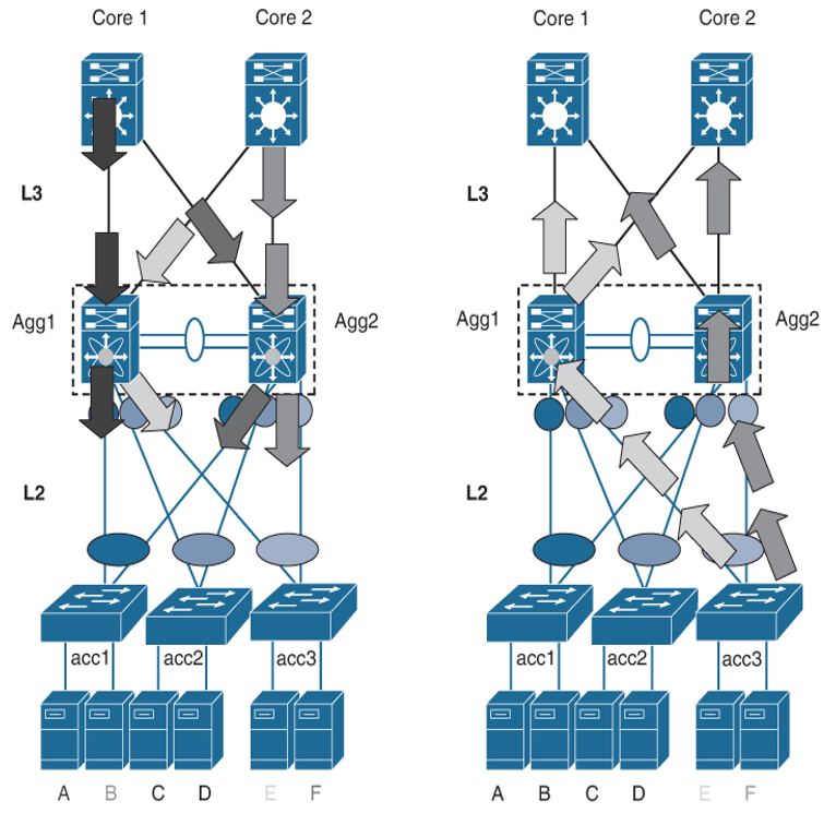
Figure 4-11 illustrates the traffic forwarding in a vPC environment. In the left diagram, the data traffic reaching Cisco Nexus switches Agg1 and Agg2 from the core is forwarded toward the access switches acc1, acc2, and acc3 without traversing the peer Cisco Nexus switch device using the vPC peer-link. Similarly, traffic from the server directed to the core reaches Cisco Nexus switches Agg1 and Agg 2, and the receiving Cisco Nexus switch routes it directly to the core without unnecessarily passing it to the peer Cisco Nexus device using the peer-link. This happens regardless of which Cisco Nexus device is the primary HSRP device for a given VLAN.

Figure 4-11 vPC Data Plane Traffic Flow
