Communicating Between VDCs
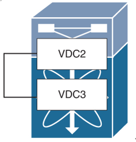
Cisco NX-OS software does not support direct communication between VDCs on a single physical device. You must make a physical connection from a port that is allocated to one VDC to a port that is allocated to another VDC to allow the VDCs to communicate. You must use the front panel port to connect between VDCs; soft cross-connect on backplane inter-VDC communications does not exist. Storage shared ports can communicate with each other within their respective VDC. There is no restriction on L2/L3 or line card models. When using vPC or vPC+ between VDCs, you have to ensure domain IDs are unique. (More on vPCs can be found in Chapter 4, “Port Channels and vPCs.”)
Figure 5-11 shows two VDCs that are connected externally but not connected internally.

Figure 5-11 Communicating Between VDCs
VDC Resources
When you’re creating VDCs, certain resources are shared across VDCs while others must be dedicated to a VDC. Three types of VDC resources can be defined:
- Global resources: These resources can only be allocated, set, or configured globally for all VDCs. These resources include boot image configuration, Ethanalyzer session, NTP servers, CoPP configuration, and in-band SPAN sessions. For example, boot string specifies the version of software that should be used upon booting up the switch. It is not possible to run different versions of the Cisco NX-OS software in different VDCs.
- Dedicated resources: These resources are allocated to a particular VDC, such as Ethernet interfaces.
- Shared resources: These resources are shared between VDCs, such as the OOB Ethernet management port on the supervisor. For example, if multiple VDCs are configured and accessible from the management interface, they must share it, and the OOB management interface cannot be allocated to a VDC like other regular switch ports. The management interfaces of the VDCs should be configured with IP addresses on the same IP subnet as the management VRF instance.
Types of Resources
VDC resources can also be classified into two broad categories: physical and logical.
Physical Resources
Network admins can allocate physical device resources exclusively for the use of a VDC. Once a resource is assigned to a specific VDC, you can manage it only from that VDC. Users logging directly into the VDC can only see this limited view of the device and can manage only those resources that the network administrator explicitly assigns to that VDC. Users within a VDC cannot view or modify resources in other VDCs.
The only physical resources that you can allocate to a VDC are the Ethernet interfaces. For the Ethernet VDCs, each physical Ethernet interface can belong to only one VDC, including the default VDC, at any given time. When you are working with shared interfaces in the storage VDC, the physical interface can belong to both one Ethernet VDC and one storage VDC simultaneously, but to no more than one of each.
Initially, all physical interfaces belong to the default VDC (VDC 1). When you create a new VDC, the Cisco NX-OS software creates the virtualized services for the VDC without allocating any physical interfaces to it. After you create a new VDC, you can allocate a set of physical interfaces from the default VDC to the new VDC. When you allocate an interface to a VDC, all configuration for that interface is erased. The VDC administrator must configure the interface from within the VDC. Only the interfaces allocated to the VDC are visible for configuration. On many I/O modules, any port can be individually assigned to a VDC. The exceptions to this rule include modules whose architecture uses port groups that consist of two, four, or eight ports each, where the ports within the same port group share some common hardware elements. In this case, ports in the same group must be assigned to the same VDC. For example, the N7K-M132XP-12 line card has eight port groups of four interfaces each, so in total 32 interfaces. Hence all N7K-M132XP-12 line cards require allocation in groups of four ports. Interfaces belonging to the same port group must belong to the same VDC.
Figure 5-12 illustrates the interface allocation for port groups on a Cisco N7K-M132XP-12 line card.

Figure 5-12 Interface Allocation for Port Groups on Cisco N7K-M132XP-12 Line Card
