
VDC Types
The use of VDCs with the Cisco Nexus 7000 Series Supervisor 2E or 3E modules allows a single Cisco Nexus 7000 Series switch to be partitioned into up to eight VDCs: the default VDC and seven additional VDCs. Another available choice is to create one admin VDC and eight additional VDCs. More than four VDCs require additional licenses. The VDC types are discussed in the sections that follow.
Default VDC
The physical device always has at least one VDC, the default VDC (VDC 1). When you first log in to a new Cisco NX-OS device, you begin in the default VDC. Initially, all hardware resources of the switch belong to the default VDC. The default VDC is a fully functional VDC with all the capabilities and can be used for production traffic with no issues. Some customers may choose to reserve it for administrative functions.
Figure 5-6 illustrates Default VDC.
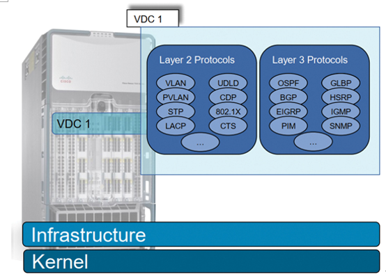
Figure 5-6 Default VDC
Some tasks can only be performed in the default VDC, including the following:
- VDC creation/deletion/suspend
- Resource allocation (interfaces and memory)
- NX-OS upgrade across all VDCs
- EPLD upgrade, as directed by TAC or to enable new features
- Ethanalyzer captures for control/data plane traffic
- Feature set installation for Nexus 2000, FabricPath, and FCoE
- Control plane policing (CoPP) configuration
- Systemwide QoS and port channel load-balancing configuration
- Hardware IDS checks control
- Licensing operations
- Reload of the entire switch
The default VDC has a special role: it controls all hardware resources and can access all other VDCs. VDCs are always created from the default VDC. Hardware resources, such as interfaces and memory, are also allocated to other VDCs from the default VDC. Other VDCs only have access to the resources allocated to them and cannot access any other VDCs.
VDCs are separated on the data plane, control plane, and management plane. The only exception to this rule is the default VDC, which can interact with the other VDCs on the management plane. Control plane and data plane functions of the default VDC are still separated from the other VDCs.
Admin VDC
You can enable an admin VDC at the initial system bootup through a setup script. It is an optional step, and the creation of an admin VDC is not required. When an admin VDC is enabled at bootup, it replaces the default VDC. An admin VDC is used for administrative functions only and is not a fully functional VDC like the default VDC. If an admin VDC is created, it does not count toward the maximum of eight VDCs on Cisco Nexus 7000 Series switches.
You can also change the default VDC to admin VDC using the following methods.
- When you enter the system admin-vdc command after bootup, the default VDC becomes the admin VDC. The nonglobal configuration in the default VDC is lost after you enter this command. This option is recommended for existing deployments where the default VDC is used only for administration and does not pass any traffic.
- You can change the default VDC to the admin VDC with the system admin-vdc migrate new vdc name command. After you enter this command, the nonglobal configuration on a default VDC is migrated to the new migrated VDC. This option is recommended for existing deployments where the default VDC is used for production traffic whose downtime must be minimized.
Once an admin VDC is created, it cannot be deleted and it cannot be changed back to the default VDC without erasing the configuration and performing a fresh bootup.
Admin VDCs are supported on Supervisor 1 and Supervisor 2/2e/3e modules. When an admin VDC is enabled, only the mgmt0 port can be allocated to the admin VDC, which means that for an admin VDC, only out-of-band management is possible through the mgmt0 interface and console port. No other physical Ethernet or logical interfaces are associated with the admin VDC.
Figure 5-7 shows the admin VDC.
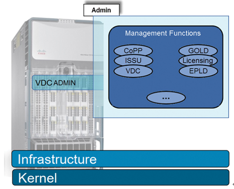
Figure 5-7 Admin VDC
The admin VDC provides access only to pure system administration tasks, including the following:
- Create, change attributes for, or delete a nondefault VDC
- In Service Software Upgrade/Downgrade (ISSU/ISSD)
- Erasable Programmable Logic Device (EPLD) upgrades
- Control plane policing (CoPP) configuration
- Reload of the entire switch
- Collection of show tech-support, tac-pac commands, run debug commands, and Cisco Generic Online Diagnostics (GOLD)
- Systemwide QoS and port channel load-balancing configuration
- Feature set installation for Nexus 2000 and FCoE
- Licensing operations
Nondefault VDC
Nondefault VDCs are created by the default VDC and are fully functional VDCs with all capabilities. Changes done in a nondefault VDC only affect that particular VDC. Nondefault VDCs have discrete configuration file and checkpoints per VDC. Nondefault VDCs run independent processes for each protocol per VDC and thus provide fault isolation. Nondefault VDCs can be of the Ethernet type or Storage type. VDCs that only have Ethernet interfaces allocated to them are called Ethernet VDCs. Ethernet VDCs don’t have any storage ports such as FCoE ports allocated to them.
Figure 5-8 shows a nondefault VDC.
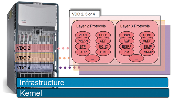
Figure 5-8 Nondefault VDC
Storage VDC
Beginning with Cisco NX-OS Release 5.2(1), Nexus 7000 Series devices support Fibre Channel over Ethernet (FCoE). To run FCoE, a dedicated storage VDC should be configured on the Cisco Nexus 7000 Series devices. The storage VDC is one type of nondefault VDC. Storage virtual device context (VDC) separates LAN and SAN traffic on the same switch and maintains one physical infrastructure, but with separate logical data paths. A storage VDC creates a virtual MDS switch within the Nexus 7000 chassis and participates as a full Fibre Channel forwarder (FCF) in the network. A storage VDC can be configured with zoning, a Fibre Channel alias, Fibre Channel domains, fabric binding, and so on. After the storage VDC is created, FCoE VLANs can be configured, and interfaces are specified as dedicated FCoE interfaces or shared interfaces. A shared interface can carry both Ethernet and FCoE traffic, however; storage traffic is processed in the storage VDC, while Ethernet traffic is processed in another Ethernet VDC. Traffic is split based on Ethertype. Traffic from the storage protocol is sent to the storage VDC, while the rest is sent to the Ethernet VDC, as you can see in Figure 5-9.
The Ethernet VDC administratively “owns” the interface. The shared port must be configured as an 802.1Q trunk in the Ethernet VDC. All ports on the ASIC (port group) must be configured for sharing. Shutting down a shared interface in the Ethernet VDC shuts down both Ethernet and storage VDC interfaces. However, shutting down a shared interface in the storage VDC only shuts down the FCoE interface, not the Ethernet interface.
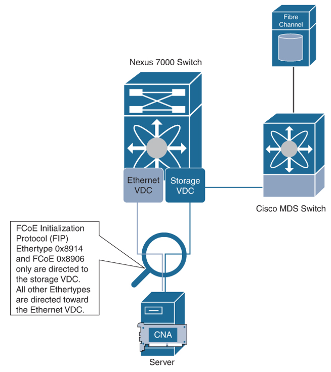
Figure 5-9 Storage VDC
Although a storage VDC does not require an advanced license (VDCs), it requires the FCoE license to enable the FCoE function on the modules. There can be only one storage VDC on the Cisco Nexus 7000 Series device. A default VDC cannot be configured as the storage VDC. Only the Cisco Nexus 7000 F-series module supports the storage VDC. The M-series I/O modules do not support storage VDCs. F1 and F2/F2e Series modules cannot be intermixed in the storage VDC.
VDC Module Type Modes
Not all line card modules support all Cisco NX-OS features and can cause problems when improperly assigned to a VDC. For example, OTV is not supported on the F1 or F2 module. To prevent widespread disruption within a VDC, you can restrict certain line cards from being assigned to a VDC by using the system limit-resource module-type command. For example, the limit-resource module-type f1 m1 m1-xl m2-xl command allows a mix of M1, M1-XL, M2-XL, and F1 modules in the same VDC.
Figure 5-10 shows three VDCs configured on the same physical Nexus 7000 Switch: M1-F1 mixed VDC, M1-XL only VDC, and F2 only VDC.
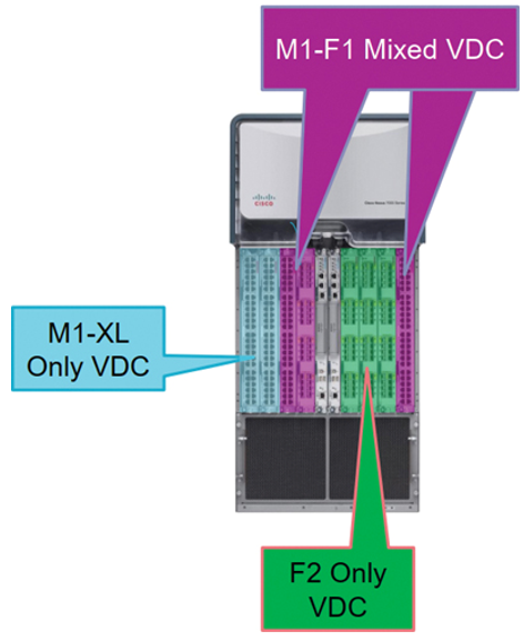
Figure 5-10 VDC Module Type Modes
Table 5-4 shows the VDC module type compatibilities for Cisco NX-OS Release 8.x, the latest version at the time of this writing.
Table 5-4 VDC Module Type Compatibility for Release 8.x
| | F1 | F2 | M2XL | F2e(F2CR) | F3 | M3 |
| F1 | True | False | True | False | False | False |
| F2 | False | True | False | True | True | False |
| M2XL | True | False | True | True | True | True |
| F2e(F2CR) | False | True | True | True | True | False |
| F3 | False | True | True | True | True | True |
| M3 | False | False | True | False | True | True |