vPC Components
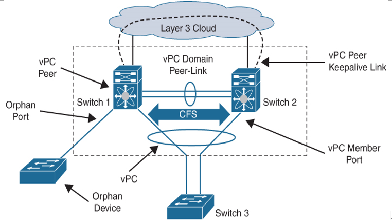
Figure 4-8 shows the components of vPC along with their naming conventions.

Figure 4-8 vPC Components
The components used in vPCs are as follows:
- vPC: The combined port channel between the vPC peer devices and the downstream device.
- vPC peer device: One of a pair of devices connected with the special port channel known as the vPC peer-link. You can have only two devices as vPC peers; each device can serve as a vPC peer to only one other vPC peer. The vPC peer devices can also have non-vPC links to other devices.
- vPC peer-keepalive link: The peer-keepalive link monitors the vitality of vPC peer devices. The peer-keepalive link sends configurable, periodic keepalive messages between vPC peer devices. It is highly recommended to associate a peer-keepalive link to a separate virtual routing and forwarding (VRF) instance that is mapped to a Layer 3 interface in each vPC peer device. If you do not configure a separate VRF, the system uses the management VRF by default. However, if you use the management interfaces for the peer-keepalive link, you must put a management switch connected to both the active and standby management ports on each vPC peer device. Do not use Ethernet crossover cables to connect the management ports on the vPC peers to each other back-to-back because the peer-keepalive link will fail on supervisor switchover. No data or synchronization traffic moves over the vPC peer-keepalive
link; the only traffic on this link is a message that indicates that the originating switch is operating and running a vPC. - vPC peer-link: The vPC peer-link carries essential vPC traffic between the vPC peer switches and is used to synchronize state between the vPC peer devices. The vPC peer-link is a port channel and should consist of at least two dedicated 10-Gigabit Ethernet links terminated on two different I/O modules, if at all possible, for high availability. Higher-bandwidth interfaces (such as 25-Gigabit Ethernet, 40-Gigabit Ethernet, 100-Gigabit Ethernet, and so on) may also be used to form the port channel. The peer-link should only allow traffic that is part of the vPC domain. If other traffic is also allowed, it could overload the link during failures. The system cannot bring up the vPC peer-link unless the peer-keepalive link is already up and running.
- vPC member port: A port that is assigned to a vPC channel group. These ports form the virtual port channel and are split between the vPC peers.
- Host vPC port: A fabric extender host interface that belongs to a vPC.
- Orphan port: A non-vPC port, also known as an orphaned port, is a port that is not part of a vPC.
- Orphan device: An orphan device is a device connected to a vPC domain using regular links instead of connecting through a vPC.
- vPC domain: The vPC domain includes both vPC peer devices, the vPC peer-
keepalive link, and all of the port channels in the vPC connected to the downstream devices. It is also associated to the configuration mode you must use to assign vPC global parameters. Each vPC domain has a vPC instance number that is shared between two devices. Only two devices can be part of the same vPC domain, but you can have many vPC domains on a single device. The domain ID can be any value between 1 and 1000, and the same value must be configured on both switches that form the vPC pair. The vPC peer devices use the vPC domain ID to automatically assign a unique vPC system MAC address. Each vPC domain has a unique MAC address that is used as a unique identifier for the specific vPC-related operation. Although the devices use the vPC system MAC addresses only for link-scope operations such as LACP, it is recommended that you create each vPC domain within the contiguous Layer 2 network with a unique domain ID. You can also configure a specific MAC address for the vPC domain rather than having Cisco NX-OS software assign the address. - Cisco Fabric Services: The Cisco Fabric Services (CFS) is a reliable state transport mechanism used to synchronize the actions of the vPC peer devices. CFS carries messages and packets for many features linked with vPC, such as STP and IGMP. Information is carried in CFS/CFS over Ethernet (CFSoE) protocol data units (PDUs). When you enable the vPC feature, the device automatically enables CFSoE, and you do not have to configure anything. CFSoE distributions for vPCs do not need the capabilities to distribute over IP or the CFS regions. CFS messages provide a copy of the configuration on the local vPC peer device to the remote vPC peer device. All MAC addresses for those VLANs configured on both devices are synchronized between vPC peer devices using the CFSoE protocol. The primary vPC device synchronizes the STP state on the vPC secondary peer device using Cisco Fabric Services over Ethernet (CFSoE).
- vPC VLANs: The VLANs allowed on the vPC are called vPC VLANs. These VLANs must also be allowed on the vPC peer-link.
- Non-vPC VLANs: Any of the STP VLANs that are not carried over the vPC
peer-link.
